
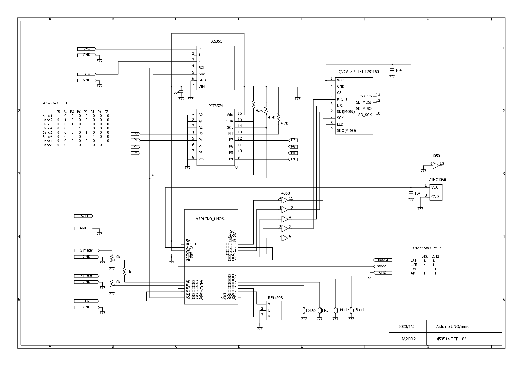
回路図
スケッチ

バンド設定は、周波数テーブルに8バンド定義した。DEF_Fは、デフォルト周波数。LOW_Fは、最低周波数。HI_Fは最大周波数である。8バンド以上に拡張する場合、PCF8574のさらなる追加とスケッチ追加、修正が必要。


EEPROMデータをクリアするには、Int_Endを49以外の数値に変更する。これは重要で、EEPROMクリアしなければ以前のデータが読み込まれて動作するので、意図しない動作をするかもしれない。EEPROMデータのデフォルト値読み込みは、STEPを押しながら電源onでも出来る。
スケッチ等のダウンロード
このVFOに必要なファイルは、ダウンロードサイトからダウンロード可能。
Download siteにあるsi5351a TFTフォルダのsi5351a_TFT18_1.3.zip
18 件のコメント:
One question, can you #devine IF_FREQ 10700000 just like BFO triple split depending on AM, LSB and USB. I have a 2.7 KHz crystal filter as 1 IF and need a USB LSB dependent lo ?
It is explained in the sketch section.
I can't find it or I have expressed myself incorrectly.
I also need three different If frequencies for LSB, USB and CW for the VFO output as with the BFO output.
I have written an email to explain what I mean.
73 de DD1MR Mike
I don't think it would be a problem to have 3 filters.
It is just outputting carrier points corresponding to the mode, so it is as per the previous answer.
However, the carrier frequency corresponding to the mode must be set correctly. (As per the sketch section)
If you cannot understand the blog and sketch program, please consider it difficult.
As a supplementary explanation, the sketch needs to be modified.
When I say that there is no problem, I interpret that my blog is being read by someone who has the skill to modify sketches.
I don't think there will be any problems because the parts that should be referenced are also coded.
As mentioned at the top of the blog, we do not do any customization.
Maybe I understand it wrong then sorry but if it is not possible to set the IF frequency for the first IF for USB and LSB with the mode switch as it works with the BFO frequency then how am I supposed to build a multiband transciver without a narrow crystal filter? Then I have built everything for nothing and spent time on the crystal filter for nothing. 😰 Unfortunately I am not good at programming. A little tip would help me...
I don't understand your transceiver design philosophy.
Generally, I think many people design one crystal filter for LSB, USB, and CW. In this case, BFO is output according to LSB, USB, and CW. The problem with this is that CW is easily affected by nearby frequencies. To solve this problem, it is effective to use a filter with a 500Hz band specifically for CW. (2 crystal filter system)
If you use an SSB filter for AM, the band will be narrow, so the sound quality will be poor. At this time, we use an AM-specific crystal filter with a band of about 3kHz to 4kHz. (In this case, the system uses three filters, as it has one for SSB, one for CW, and one for AM.)
I think what you are talking about as a narrow filter has a band of around 2.7kHz, which is the common band used for SSB. Some people use something with a band around 2.4kHz.
I think there is no problem with a system with one 2.7kHz band filter.
Hi again, how can I use the shift function and is it for ifshift. I think that would help me a lot if I could use the VFO + ifshift for USB, LSB and CW instead of the fixed If.
I still have a lot to learn and have only been a Hamradio operator for two years.
73 de DD1MR
👍
There is nothing except the variable name ifshift.
Even if you ask me a question, I have no idea about your H/W specifications.
I don't think anyone can answer your question.
Please solve it yourself.
I'm sorry but I won't reply.
おはよう
TFT 3.1 バージョンのコードをロードできません。ROTARY.CPP がコンパイルできません。すでに Web サイトからダウンロードしましたが、ARDUINO_IDE 2.2.1 を使用しているかどうかわかりません。デバイスは NANO です。 、ヒントやビデオはありますか?
TFT3.1とこちらのVer1.3は、バージョンが示す通り互換がありません。
回路が異なっているので動作しません。
Arduino IDEのバージョンは関係ありません。
回路図をよく見てください。これ以上の説明もビデオもありません。
はい、3.1 で使用しているディスプレイは 240*320 であることに気付きましたが、128*160 を使用できますか? すべての文字が含まれますか? どうすればこれを変更できますか?
このバージョン 3.1 をテストしたいと思います。
助けてくれてありがとう、うまくいきましたが、コード内の表示がタッチ モデル LLI9341 2.4 TFT240*320 であることがわかりました。来週注文しました。ここにあります。はい、作成した回路を修正します。うまくいくと信じています。 このバージョンにはメニューがありますか、それともコンパイル前にコードを通じてすべてを実行しますか?
スケッチがメモリーに収めるのが限界で、メニューシステムは有りません。
もしメモリーに余裕があっても、メニューは作りません。
分かりました、
プログラミングはあまり得意ではありませんが、ハードウェアは得意です。モードごとではなくバンドごとに BFO を記述することは可能でしょうか? 私が接続しようとしているラジオは少し異なり、バンドごとに 9MHZ 発振器とクリスタル、そして 5.5MHZ VFO を備えています。
ラジオ自体の 9 周波数と VFO の 5.5 周波数を使用して BFO でクリスタル周波数を生成することが可能だと思います。それが完璧だと思います。正しくなるまでここで実験してみます。
良い一年と健康をお過ごしください。日本では 2 月 4 日から始まると思いますが、ここブラジルでは明日で一年が終わります。
コメントを投稿